Antenna Design Simulations for IoT5GPIFA .
Wireless communication for smart products means antennas everywhere.
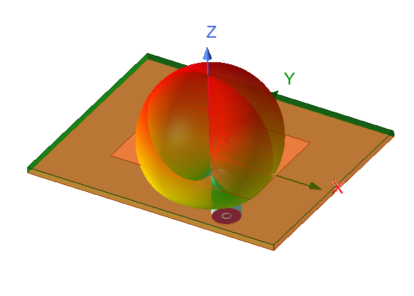
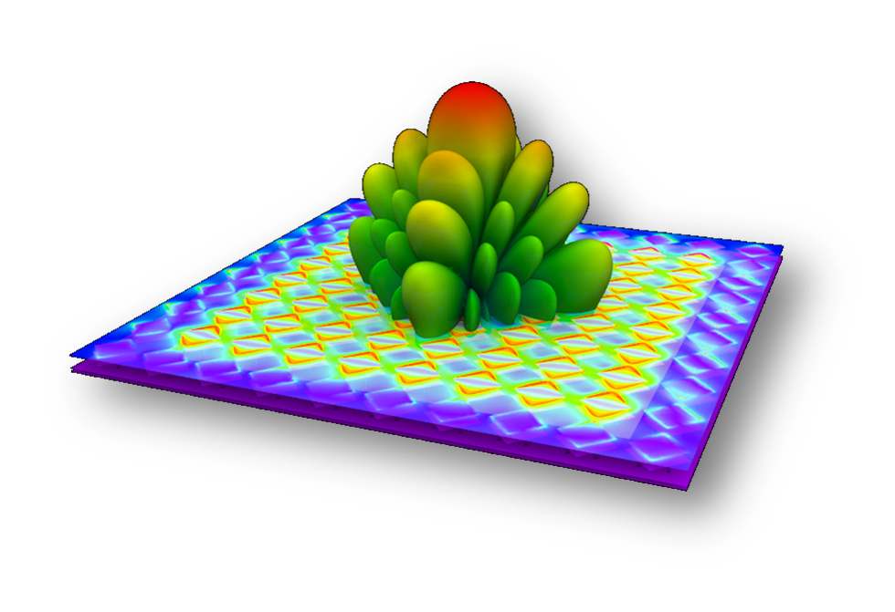
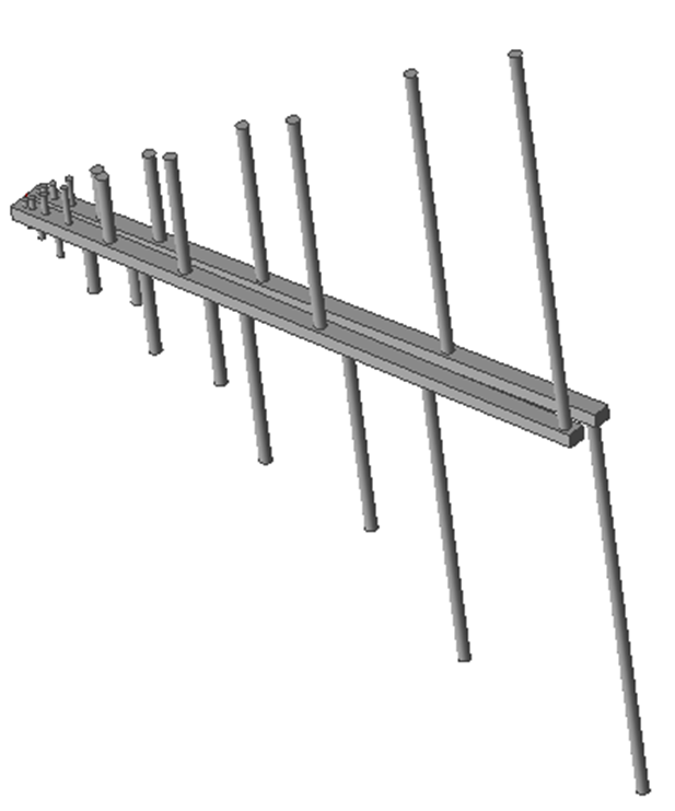
Engineers design, optimize and integrate antennas with Ansys HFSS. HFSS automatically computes standard antenna metrics such as gain, return loss, input impedance, radiation efficiency and full 3D near and far field patterns. Dynamic electromagnetic-circuit co-simulation with Ansys Designer provides rigorous end-to-end analysis for an antenna system including, for example, effects of transceiver network integration on beam patterns and steering for antenna arrays. For planar antenna designs such as patch or meander line PCB antennas, HFSS provides a 2.5-D method of moments solution in an easy-to-use 2-D drawing interface for fast analysis of layered 2D designs.
What is Antenna?
Antenna is an electrical device (transducer) used to transform electrical power to RF waves, and vice versa.
 For designing an antenna, as an antenna design engineer, you need to know, what is the desired frequency, gain, bandwidth, impedance, and polarization? If you never heard of these parameters, these are antenna fundamental parameters which characterize an antenna.
Antenna Fundamental Parameters:
- Frequency
- Bandwidth
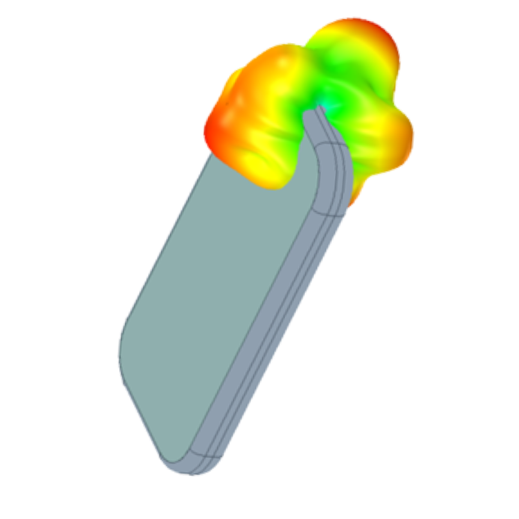
- Radiation Pattern
- Directivity
- Radiation Efficiency
- Gain
- Polarization
- Return Loss
- Impedance
 Today’s Small Antenna Requirements :
- Multiband
- High Efficiency
- Working in complex environment
- Cost effective
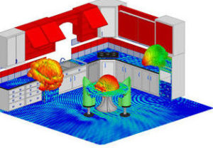
Ansys Electromagnetics products predict antenna design performance and EMI-EMC failures for wide variety of applications:
- Mobile phones, smart wearables, tablets, PCs, hearing aids, MP3 players, laptops, TVs, gaming consoles
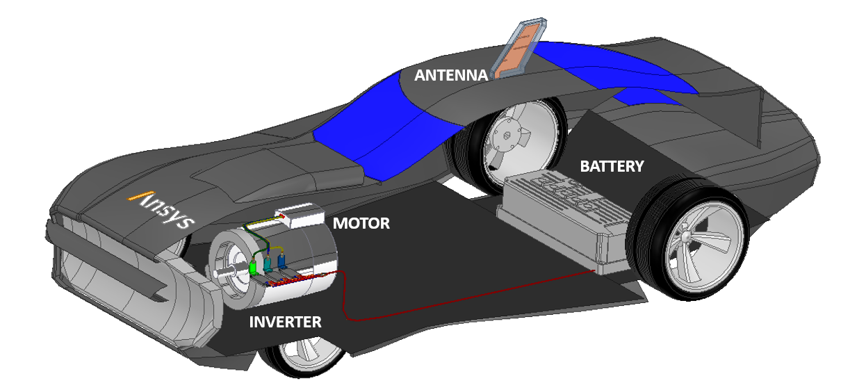
- Automotive telematics, infotainment, navigation and driver assistance
- Telecommunications networks
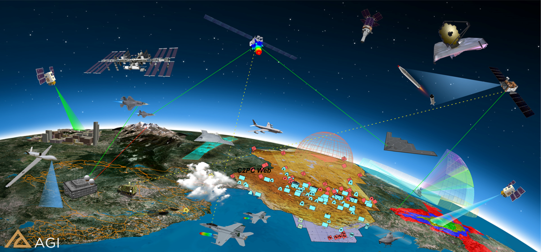
- Aerospace, military and satellite communications
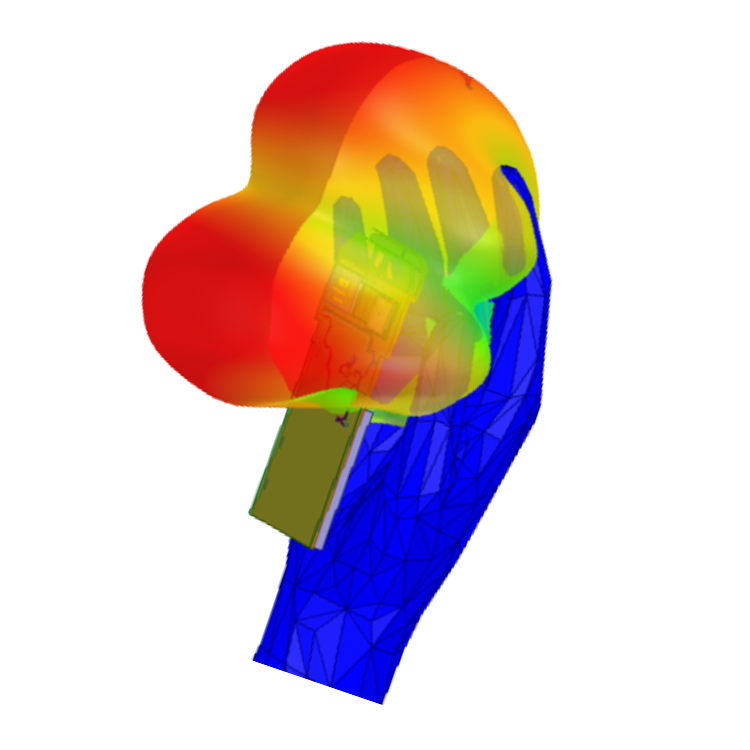
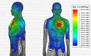 The wide and fast growing application of wireless devices yields to a lot of concerns about their safety standards. The Specific Absorbtion Rate (SAR), which measures the electromagnetic power density absorbed by the human body tissue, is considered as an index by FCC to regulate the amount of exposure of the human body to electromagnetic radiation.
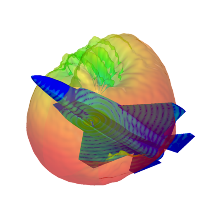
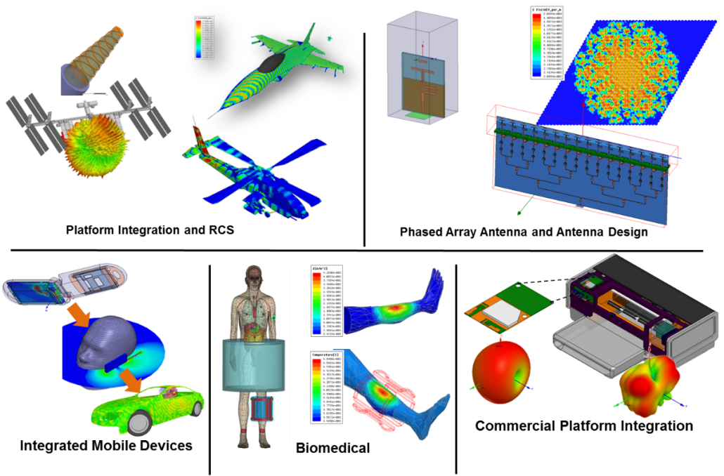
Antenna integration is a complex multi-scale and multi-domain problem. The major challenges in antenna integration modeling are accuracy, electrical size and scale, geometric complexity, platform materials, placement and co-site interference, and solution time. The antenna performance/characteristic can be affected after integrating on the platform (Far-Field pattern degraded, input impedance detuned…). Successful Integration of antenna systems on platforms requires that the design engineers overcome these challenge. Here are some tips and tricks to overcome the challenges:
- De-feature models obtained from mechanical or electrical CAD tools when possible. (These models typically include geometry details insignificant for electromagnetic analysis)
- Removing unnecessary model details reduces mesh density and runtime. (Use good engineering judgment to make certain that removed features are electrically insignificant)
- Using Ansys Electronics High Performance Computing (HPC) to reduce run time.
- Using HFSS Hybrid Solution (Integral Equation, Physical Optics) or HFSS integration with SAVANT for large electrical size and scale.