Electrical Infrastructure – Power Cable Ampacity Solutions
There cannot be a real discussion about solving the world’s electric power requirements without seriously considering the ampacity of the power cables used in the transmission and distribution of the power from the sources (generator, solar, wind, plasma fusion, etc.) to the customer loads consuming power.
FEA solutions must be used for any case that is not covered by the standards and these are not limited to convective and radiative heat transfer problems. Power cable installation examples for which conductive heat transfer problems require FEA solutions include multiple duct banks, cooling/heating pipes around duct banks, and when the soil has several layers of different materials.
There are many cable installations that do not have a good standard. Here are a few examples but there are a lot more:

Cables in tunnels (differing size, carrying different loads, no standard)
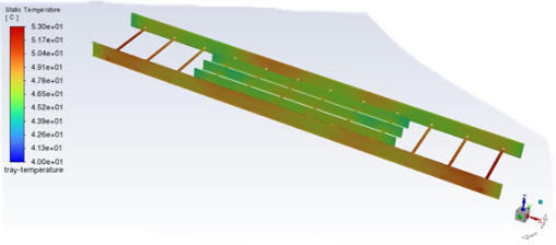
Cables in trays (ladder, solid bottom, covered and uncovered)
Cables in riser poles (vented or not)
Cables in troughs
Cables in J tubes
Fire protected cables
Duct banks with large aspect ratios
Duct crossings
Multiple duct banks
Bentonite in ducts
Ducts in tunnels
Cable Joints
Cables with rain
Busbars
Longitudinal flow
There are many other things that are not considered in the standards correctly. In particular, the magnetic behavior is mostly wrong. Circuits are considered magnetically decoupled even when we know they are very coupled. This is well documented. Also, FEA can simulate 3D models of any type of power cable installation, while popular competitor template-based software is limited to standard 2D model installations.
Design Methodology
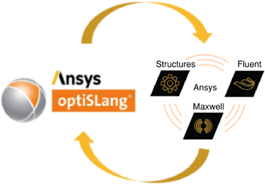
The Ansys design tools include industry-based material libraries and multi-physics capability to allow designers to make guided technical decisions in the power cable design selection process.
Geometry
- Import into Ansys or create using Ansys CAD tools.
- Objects include cable and layers (single-core, trefoil, three-core, etc.), and may include ducts, tunnels, backfill, soil, etc.
Material Properties
-
Determined from standards (NEC, IEEE, or IEC) or from manufacturer specification sheets.
Mesh
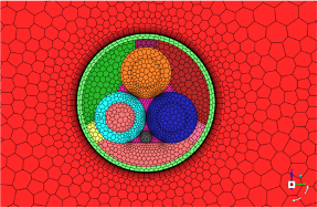
- Ozen engineers have substantial experience and knowledge to produce high quality meshes and have challenging CFD simulations to converge.
- Thermal boundary layers are computed, and meshing techniques are applied to increase mesh quality while minimizing the number of mesh elements.
Physics
- Heat sources are computed using standard equations (NEC, IEEE, or IEC) or using ac/dc ratios and loss distributions given by cable specification sheets.
- Ansys Maxwell is used to solve for electromagnetic losses and couple with CFD when standard heat source equations are not used.
- Conjugate Heat Transfer solvers are used when there is conductive and convective heat transfer in the model and CHTs are used on BCs.
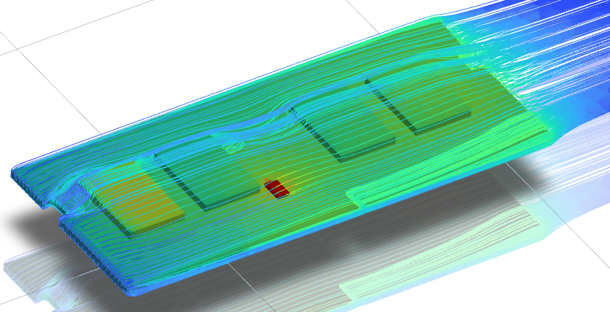
- CFD is used when there is convective heat transfer in the model and fluid flow field is solved.
- Radiative Heat Transfer solvers are enabled when there is radiative heat transfer between surfaces.
Validation
- Designs are validated using data from manufacturer data sheets.

Ansys Structures

Ansys Fluent

Ansys Maxwell
Determination
Ampacity of a power cable depends on the specific installation and operation conditions as described below:
Installation
- External thermal resistance (most important)
- Thermal properties between the cable surface and the ambient air (air or other fluid within cable enclosure, duct walls, tunnel walls, soil, backfill, ocean water, etc.).
- FEA models do not require using an equivalent (effective) external thermal resistance.
- FEA models can easily and realistically represent underground material (soil, backfill, etc.) with varying thermal properties.
- The sheath bonding type is the second most important parameter.
- Solid Bonding is always used in the USA. Other countries may use Solid Bonding, Cross Bonding, or Single Point Bonding.
- Ambient temperature.
- Depth (if buried).
- Conductor size and material.
- Cable layers and materials.
- Number of cables (loads) and proximity to between cables.
- Solar radiation.
- Enclosure clearances.
- Ventilated (forced convection) or non-ventilated (free convection)
Operation
- Operating time, load factor, varying load cycle, operating frequency (DC or AC).
- Emergency load transfers.
Multiphysics & Standards
Determination of power cable ampacity is a multi-physics task. The heat source equations used in the standards were derived from electromagnetic theory and applied to heat transfer theory.
Electromagnetics: Maxwell’s equations are the governing equations to compute the losses due to the:
- Skin and proximity effect
- Dielectric (insulation)
- Sheath and armor
- Duct or pipe enclosing the cable.
Conservation of energy: The losses are applied in the conservation of energy so that power loss in the cable, heat generated via conduction, is equal to the heat transferred out of the cable.
The three modes of heat transfer are:
- Conduction: Heat generated in and transferred out of solid objects (cable and layers, enclosure walls).
- Convection: Heat transferred by fluid (air, water, oil, etc.).
- Radiation: Heat transferred by between surfaces (cables, enclosure walls, etc.).
Fluid Flow: The Navier-Stokes equations are the governing equations to determine fluid flow in convection heat transfer and these are solved using CFD.
Results may include:
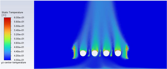
- Temperature distribution plots of conductors and system
- Fluid flow plots of air around cables and system.
- Temperature transient plots of conductors and cable layers.
- Compare convective and radiative heat transfer values to determine the dominant mode.
Optimization
Regarding optimization & robust design solutions there is a need for efficient optimization techniques which can offer data-driven exploration of the design space while utilizing multi-physics simulation:
- The power cable system design space is large with complex interactions.
- Use of OptiSLang enables:
- Class-leading multi-physics power cable system optimization.
- Traceability on design decisions and data-based trade-off analysis.
- Efficient multi-objective design optimization and fast response to changing requirements.
- Robust design insights.
Find personalized Ansys solutions with Ozen Engineering
Ozen Engineering offers best-in-class simulation tools, project consulting, software training, mentoring and technical support services.
We deliver solutions that are customized to meet your unique needs, whether that be mentoring on the most efficient use of a single simulation product or a comprehensive evaluation of your current simulation processes with a roadmap for improvement.
Consulting
We’ll help you solve your product design challenges using Ansys solutions.
Mentoring
We’ll show you how to use Ansys simulation more effectively and efficiently.
Training
We’ll help you solve your product design challenges using Ansys solutions.
Customer Testimonials
We really enjoyed working with Pat and his team at Ozen Engineering. They were professional and responsive, and really helped us out – we have put the FE analysis results to good use and used it to design a sensor layout that is now undergoing fabrication and soon testing.

Ozen Engineering, Inc. helped our business by accelerating the EM simulation. Before working with Ozen, we had problems with difficult to use CAE software I’m Venkat Kalkunte and I’m the CEO of Airfide Networks. Airfide is a 5G systems company whose expertise spans millimeter wave and c-band 5G relays and CPE. Working with Ozen helped us complete the C-band antenna in rapid time. This has allowed us to expand our portfolio of repeaters. I would strongly recommend Ozen Engineering, Inc. to anyone who needs help with EM simulation, ray tracing.
Principle Power has been working with Ozen engineering for many years. Ozen has supported Principle Power’s efforts to lead the floating offshore wind industry development by providing flexible software solutions, and software support as we move through a high growth period.

Ozen Engineering, Inc. (OEI) has been an anchor point for learning new Ansys features and executing new/novel projects. Looking back over almost 30 years’ experience w/ Dr. Metin Ozen and the OEI team, I was able to successfully complete “industry-first” (based on the publications)” finite element models of flow-induced vibration and thermally induced shock in the disk drive industry. Recently, the OEI’s support for the integration of Ansys mechanical/optiSLang/Python enables Exo to develop world’s-best class pMUT designs with accuracy and speed.
I would strongly recommend OEI to anyone, whether they who are experts or beginners in the FEA/CFD areas.

Ozen Engineering has been a trusted partner to our company for more than 15 years, always providing excellent support service and sharing their deep expertise on ANSYS to help us debug and optimize complex multiphysics simulations.
I am glad our ANSYS support is now handled by Ozen Engineering. Their quality and responsiveness for support has been great. Also, having a stable, more personal, representative contact is a welcome improvement over the direct service that ANSYS was previously supplying.
Working with Ozen engineering, inc had a very positive impact to our silicon photonics design team at Alpine optoelectronics. I am David Zheng, Vice president of Silicon Photonics from Alpine. Our company designs optical transceiver chips used in the high end mega data centers. We use HFSS for RF simulation, and Lumerical for our optical routing, high speed optical transmitter and receiver designs. Working with Ozen helped us to resolve many technical issues encountered during the use of those software. I would strongly recommend Ozen Engineering, inc, to colleagues working in the silicon photonics domain.
The team at Ozen worked through a fairly complex project with sound guidance and execution. Building on the basic model, the engineers methodically developed more complexity in the model and analyses until we arrived at a “ready to test” solution. Through multiple iterations, I really appreciated the regular check-ins, detailed project updates, and transparent billing. It was a great working relationship from the initial engagement and proposal to the end of the project. Looking forward to the next project!

Bimotal is a US company formed in 2019 to produce world-class electric powertrains for bicycles and other multimodal transportation. Bimotal systems seamlessly integrate human and motor power in small, convenient, retrofittable, lightweight, and removable form factors. Doing this requires advanced simulation tools, and support for using those tools. Ozen Engineering, Inc. has been a great partner helping us spool up with ANSYS simulation tools which allows us to improve our motor and drive unit design rapidly through FEA/FEM. Ozen not only helps with licensing but also guides their customer’s understanding of the tools so they can be used to their maximum capability. I would strongly recommend Ozen Engineering to other technology startups looking to improve their analysis capabilities to take their company to the next level!
Having worked with Ozen Engineering for many years now, I am impressed with their knowledge and dedication to supporting their customers. They have a great team with expertise across multiple disciplines that has been beneficial in Cepton’s growth.






![Ansys-elite-channel-partner-horizontal-reversed[1]](https://www.ozeninc.com/uploads/2022/06/Ansys-elite-channel-partner-horizontal-reversed1.png)