Miniaturized IOT Antennas – What is the Size Limitation?
If you have a project involving miniaturized IOT antennas, we can help you with the engineering and design by providing Ansys simulation software, training, and support as well as our consulting services.
[maxbutton id=”3″ url=”/contact-us/” text=”Contact Us” ]
Introduction:
Nowadays, wireless communication devices such as IOT place extreme requirements on efficient, miniaturized, and wideband antennas [1]. The antenna designer is faced with the challenging question of whether he could design an antenna to meet these specifications in such limited space. Early in a design cycle it is important to determine if the physical volume specified is, in theory, large enough to allow the design of any antenna which can meet the impedance bandwidth and efficiency requirements.
There is a practical limit to the bandwidth and radiation efficiency of electrically small antennas [1-7]. Knowing these physical bounds, will help IOT antenna designer prevent diverting resources to solve insurmountable problem. Physical bounds provide information about the maximum achievable performance of antennas. Bounds are derived, in general, independently of antenna geometry, material, and type [1-7].
There are well established miniaturization techniques for antenna design [9]. These techniques use antenna dielectric and lumped element loading, introduction of ground plane and short circuits and geometry optimization. These techniques can also be combined to further minimize the antenna size.
Small Antenna Bounds:
An electrically small antenna, is defined by Wheeler [2] as satisfying, the following equation:
![]()
k = 2π/λ (radians/meter)
λ=c/f free space wavelength (meters), c speed of light and f is operating frequency.
a=radius of sphere enclosing the maximum dimension of the antenna (meters).
The bandwidth of an antenna is defined as “the range of frequencies within which the performance of the antenna, with respect to some characteristic, conforms to a specified standard” by the IEEE in [10]. Typical antennas specs are impedance matching, radiation efficiency, radiation pattern, gain, polarization, etc.
Most IOT devices operate in rich scattering propagation environment. In such situations, the antenna pattern, gain, and polarization degradation are not critical. The focus of IOT antenna designer is then on maximizing impedance bandwidth and radiation efficiency. However, the antenna bandwidth and efficiency are not independent from each other and are related to the Q-Factor of the antenna.
For a single tuned mid-band matched antenna, the bandwidth is related to Q-factor by [13]:
![]()
For a double tuned mid-band matched antenna (Wheeler-Fano, n=2), the bandwidth is related to Q by [13]:
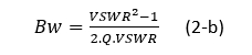
where VSWR is the voltage standing wave ratio, Q is the antenna quality factor and normalized bandwidth B is related to the operating frequency by:
![]()
where f0, f1 and f2 are the center, the lower and upper operating frequencies respectively. Using equation (2) and for VSWR=2; BW=0.707/Q for a single tuned matching and BW= 1.73/Q for double ladder tuned matching. Also, worth mentioning that for an infinite-tuned matching (Fano-Bode, n= ∞) BW =2.85/Q [13]. Equation (2) suggest that to maximize antenna bandwidth one needs to minimize the Q factor. However, as we will see later there a minimum achievable value of Q for given antenna design space.
For an antenna matched with a lossless network:
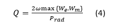
Where We is the antenna stored electric energy and Wm is the antenna stored magnetic energy. Prad is the antenna radiated power, and ω=2πf. Hence, the Q-factor for an antenna is defined as the ratio between the maximum of the stored electric, We, and stored magnetic, Wm, energies, and the radiated power Prad. The difference among various results in [1-8] is due to how the stored energies are evaluated. A good summary of these results is given in [1].
It has been well established that for an electrically small antenna, contained within a given volume, the antenna has practical limitation on Q [1-6]. Wheeler [2] and Chu [3] were the first authors to quantify the fundamental physical limitation on electrically small antennas. They showed that the minimum radiation Q, a measure of antenna bandwidth, is bound by the operating frequency and the antenna available physical size.
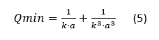
Chu [1] derived the minimum Q for an antenna contained in a sphere of radius a, for the lowest TM1 mode, as:
Most IOT antenna do operate close to a ground plane. Sten et al. [12] evaluated the limits on the fundamental Q of an electrically small antenna near a ground plane. Figure 1 Shows a plot of minimum Q factor using equation (5) and calculation in [12]. As expected, the presence of ground plane increases the minimum Q and hence lower bandwidth. It can also be concluded from Figure 1 that large antennas require bigger ground plane for proper operation.
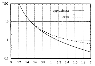
Figure 1. Q factor vs ka using equation (5) and exact curve derived in [12].
Bancroft [11] gave the expected maximum bandwidth which could be obtained from vertically and horizontally electrically small antenna enclosed in a circle of radius R over large ground plane. The results are shown in Figure 2. As expected, the bandwidth of a horizontal dipole is a lot smaller than the vertical dipole because of ground reflection effect.
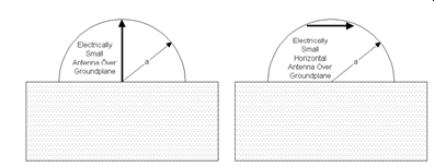
Figure 2 Vertical and horizontal small antenna over a large ground plane and their enclosing spheres
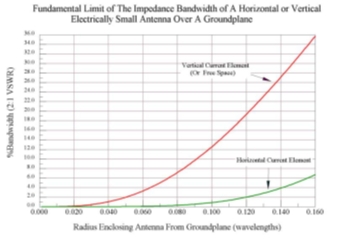
Figure 3
Antenna Design Example:
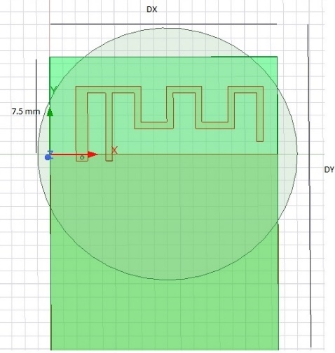
We consider the example of an inverted F antenna operating at 2.45 GHz. The width of the ground plane is Dx=17.5 mm. We use HFSS for the antenna simulation. We simulated the antenna with varying ground plane length from 25 to 45mm.
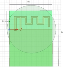
Figure 4 Inverted F Antenna.
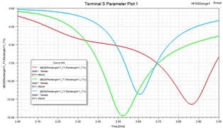
Figure 5. Reflection coefficient |S11| dB for ground plane lengths: 25, 35 and 45 mm.
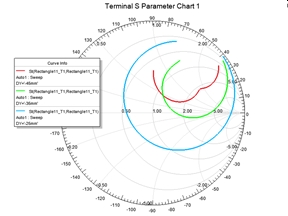
Figure 6. Smith Chart Impedance locus for ground plane lengths: 25, 35 and 45mm.
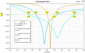
Figure 7. Lumped element matched |S11|dB for ground plane lengths: 25, 35 and45 mm.
As shown in Figure 6, the impedance locus is tighter for larger ground plane size. A tighter impedance locus gives wider bandwidth. Figure 7 shows the matched |S11| of the antenna with a one stage LC lumped circuit. The -10dB bandwidth are: 24 %, 11.5% and 6% for ground lengths of 45, 35 and 25 mm respectively. The minimum radius enclosing the antenna is 10 mm (ka=0.52). The calculated Q factor based on Figure 1 and using ka=0.52 is Q=10. The calculated bandwidth for S11=-10 dB using equation 2 is 7%. This is very close to 6% bandwidth calculated using HFFS.
Conclusion:
We have shown in this study that there is an upper limit of achievable small antenna bandwidth for a given efficiency. It is crucial to understand the antenna operation and include any critical ground plane size in estimating a radius of the enclosing sphere when estimating the antenna bandwidth. Also, proper estimation of the antenna losses is needed as losses result in increased impedance bandwidth.
References
[1] W.A. Davis, T. Yang, E.D. Caswell, W.L. Stutzman, “Fundamental limits on antenna size: a new limit” IET Microwaves Antennas & Propagation September 2011 5(11):1297 – 1302
[2] H.A. Wheeler, “Fundamental Limits of Small Antennas,” Proceedings of The I.R.E. (IEEE), December 1947, pg. 1479-1484
[3] L. J. Chu, “Physical Limitations on Omni-Directional Antennas,” J. Appl. Phys., Vol. 9, pp. 1163-1175, 1948.
[4] Roger F. Harrington, “Effect of Antenna Size on Gain, Bandwidth, and Efficiency,” Journal of Research of the National Bureau of Standards—D, Radio Propagation VOL. 64D, No. 1, January-February 1960, pp. 1-12
[5] Steven Best, “Optimization of the Bandwidth of Electrically Small Planar Antennas” MITRE Corporation approved for public Release case# 09-4198.
[6] James S. McLean, “A Re-Examination of the Fundamental Limits on The Radiation Q of Electrically Small Antennas,” IEEE Transactions on Antennas and Propagation Vol 44, NO. 5, May 1996, pg. 672-675